1535 nm rangefinder BOM
Inside a 1535 nm laser rangefinder
Eight parts carry the complete transmit, receive, timing and mechanical chain. The page preserves the supplied BOM's teaching boundary while mapping the laser and detector slots to real 1535 nm transmitter and InGaAs APD catalogue families.
- 1Pick a part from the bill of materials.
- 2Drop it on the module, or just click the card.
- 3Read its job, its parameters and the part numbers behind them.
Bill of materials
Every part, one optical budget. Drag a card onto the photo, or click it - the panel beside it fills in with that part's parameters.
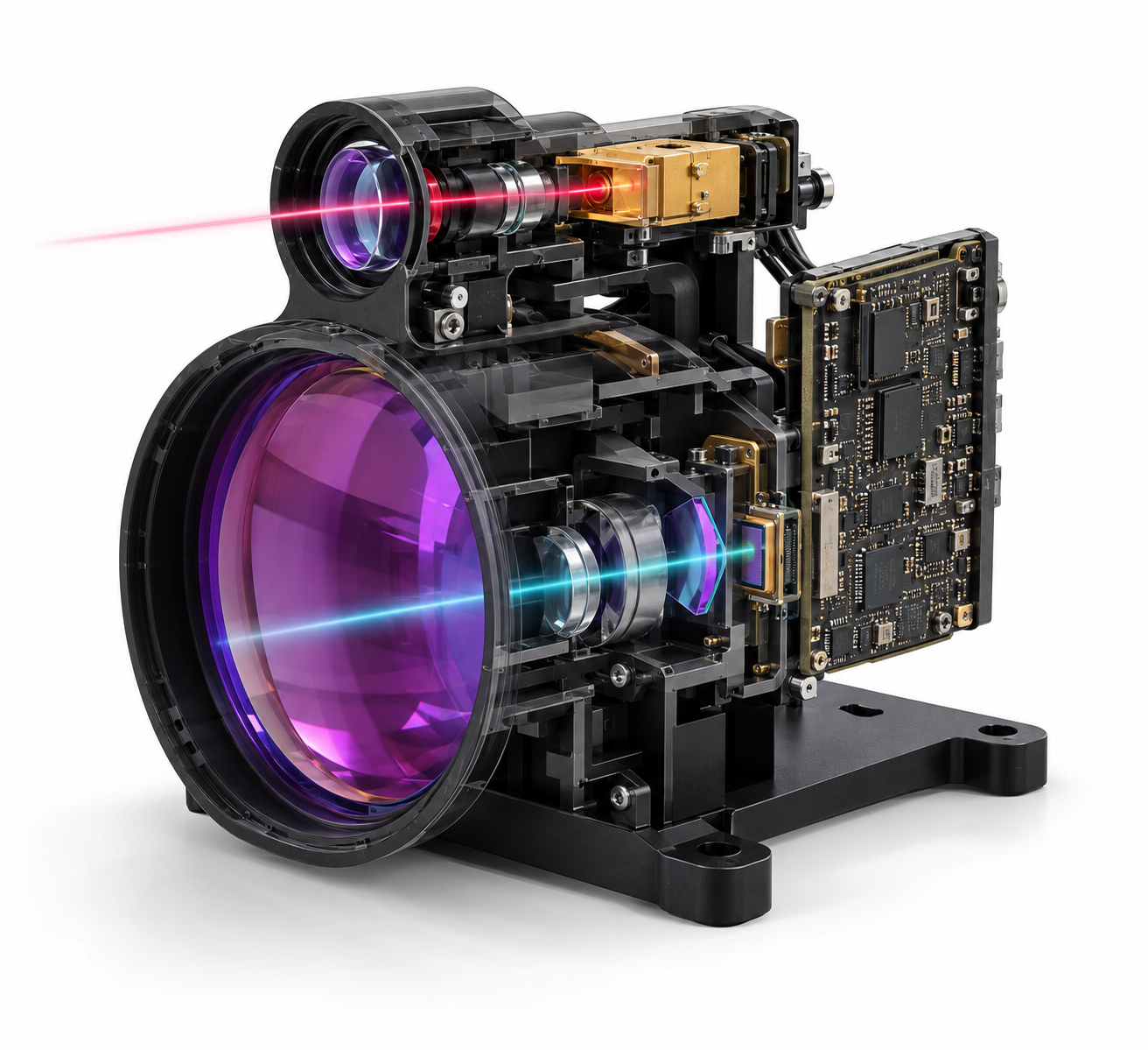
Drag a part here or click a card in the bill of materials
Teaching cutaway, not an assembly drawing. Positions are indicative; the public reference model's dimensions and ratings do not define the linked catalogue parts.
Component positions are a teaching diagram, not an assembly drawing: the placement and the exploded view are indicative. Parameter values are those of the linked specification.
Every part, parameter by parameter
The same numbers the interactive view shows, in tables you can read, search and quote.
1535 nm erbium glass laser Transmitter
Pulse energy sets the optical budget, pulse width sets timing resolution and the transmitter divergence must be matched to the transmit optics.
| Wavelength | 1535 nm |
|---|---|
| Pulse energy | >= 200 uJ |
| Pulse width | 4 ns typ |
| Repetition rate | 10 Hz |
| Beam full divergence | <= 11 mrad |
Transmit collimation and beam expansion Optics
Controls divergence, spot size at range, transmit efficiency and boresight relative to the receiver.
| Design wavelength | 1535 nm |
|---|---|
| Function | Collimation / expansion |
| Clear aperture | Application-specific Set by your design |
| Transmission | To be measured Set by your design |
| Boresight error | To be specified Set by your design |
Receiver objective Receive optics
Receiver aperture, focal length, field of view and transmission set how much return signal reaches the detector.
| Function | Return-light collection |
|---|---|
| Receive aperture | Reference drawing, confirm Set by your design |
| Focal length / field | Application-specific Set by your design |
| Coating | 1535 nm receive band |
1535 nm narrow-band filter Spectral filter
Bandwidth, peak transmission and incidence-angle tolerance decide the received signal and the background-noise budget.
| Centre wavelength | 1535 nm |
|---|---|
| FWHM bandwidth | To be selected Set by your design |
| Peak transmission | To be confirmed Set by your design |
| Incidence angle | To be specified Set by your design |
| Temperature shift | To be measured Set by your design |
InGaAs avalanche photodiode Receiver
Responsivity, gain, dark current, capacitance and bias determine receiver sensitivity, bandwidth and noise.
| Response spectrum | 900 - 1700 nm |
|---|---|
| Responsivity | 9.5 A/W @ M=10 |
| Active diameter | 230 / 500 um |
| Response time | 1.0 ns |
| Dark current | 5.0 nA @ M=100 |
| Reverse breakdown voltage | 40 - 70 V |
Transimpedance amplifier and analog front end Analog electronics
Transimpedance, bandwidth, input capacitance and noise decide whether the return can be detected without destroying its timing edge.
| Input | APD photocurrent |
|---|---|
| Transimpedance | To be selected Set by your design |
| Bandwidth | Matched to pulse width Set by your design |
| Input noise | To be measured Set by your design |
Timing and signal-processing PCB Digital electronics
Timing resolution, threshold strategy, averaging and interface latency set precision, update rate and integration effort.
| Ranging method | Time of flight |
|---|---|
| Timing resolution | To be specified Set by your design |
| Update rate | Reference model 1-10 Hz |
| Interface | RS422 / TTL (reference model) |
Enclosure, mounts and electrical interface Mechanical
Structural stiffness, thermal expansion and mounting flatness affect boresight stability; connector placement affects integration and serviceability.
| Reference envelope | 78.5 x 62 x 78.5 mm |
|---|---|
| Reference mass | 230 g |
| Mounting datum | To be released Set by your design |
| Environmental sealing | To be specified Set by your design |
Every parameter value on this page is pulled from the catalogue record that renders the linked product page, so the two cannot disagree.
Parts behind these parameters
Every figure below is read from the same catalogue record that renders the product page. Nothing on this page is retyped.
1535 nm transmitter candidates
Choose by pulse energy, repetition rate, envelope and beam divergence, then verify the drive module and thermal path.
Receiver detector
The catalogue InGaAs APD covers the 1535 nm return while keeping active-area and bandwidth options visible.
Transmitter power modules
Match the power module to the chosen pulse energy and operating current rather than sizing it from the rangefinder's input voltage alone.
Transmit, collect, filter, detect, time and report
A 1535 nm transmitter launches a short pulse through the transmit optics. The receiver objective collects the return, the narrow-band filter rejects background light, and the InGaAs APD converts the remaining signal into current. The analog front end shapes that pulse, the timing board resolves the round-trip interval, and the enclosure holds both optical axes in alignment. The supplied page cites public model ETYS2-12KX-1 only as a reference; energy, pulse width, APD material and internal layout must be confirmed against the actual engineering release.
Match the source, receiver and timing budget
Send the target range, target reflectivity, pulse energy, repetition rate, receiver aperture and interface requirement. We will narrow the transmitter, APD and power-module choices together.