Laser engraving teardown
Anatomy of a 450 nm laser engraver module
A compact engraver head is a chain of optical and thermal decisions: the 450 nm source, fast-axis collimation, the focus group, the driver and the heat path. The housing and interface set the envelope around them. Pick a part from the reference bill of materials and drop it on the cutaway to see the parameters and the 450 nm catalogue parts behind the source.
- 1Pick a part from the bill of materials.
- 2Drop it on the module, or just click the card.
- 3Read its job, its parameters and the part numbers behind them.
Bill of materials
Every part, one optical budget. Drag a card onto the photo, or click it - the panel beside it fills in with that part's parameters.
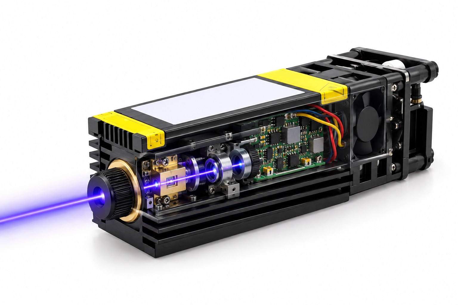
Drag a part here or click a card in the bill of materials
A teaching cutaway, not an assembly drawing. The 450 nm source and shaping optics are on the left, the driver board and fan at the rear-right, and the heatsink forms the body.
Component positions are a teaching diagram, not an assembly drawing: the placement and the exploded view are indicative. Parameter values are those of the linked specification.
Every part, parameter by parameter
The same numbers the interactive view shows, in tables you can read, search and quote.
450 nm laser source Light source
Sets the wavelength, the available optical power and the thermal load of the head. The three catalogue options are different delivery formats, not interchangeable power classes: a collimated head, a 3 W fibre module and a 30 mW alignment source.
| Wavelength range | 430 - 463 nm |
|---|---|
| Rated output | CW 5 - 5.5 W per emitter |
| Options on this line | 5 - 5.5 W collimated | 3 W fibre | 30 mW reference |
| Package | TO9 / LD bank (8 x LD + collimation) |
| Fibre delivery | 400 um multimode, SMA (3 W version) |
| Alignment source | 30 mW single-mode, FC/PC |
Fast-axis collimation / beam shaping Beam shaping
Sets the beam aspect ratio and how much of the diode's light can be put into the engraving spot. A mismatched FAC clips light or leaves an elliptical spot that the focus lens cannot correct.
| Optical form | Cylindrical lens or FAC: to be specified with the source Set by your design |
|---|---|
| Compression ratio | To be specified from the fast-axis divergence Set by your design |
| Clear aperture | To be specified with the beam size Set by your design |
| Tilt / spacing | Set by the optical design and alignment Set by your design |
| Coating | 450 nm AR coating: to be specified Set by your design |
Collimating / output optics Output optics
Turns the source's output into the spot that actually engraves. The same laser can produce a fine marking spot or a wider cleaning spot depending on this group.
| Lens material / coating | 450 nm high-power AR: to be specified Set by your design |
|---|---|
| Focal length | To be specified with the spot and working distance Set by your design |
| Spot size at the material | To be measured after assembly Set by your design |
| Working distance | To be specified with the machine envelope Set by your design |
| Clear aperture | To be specified with the beam size Set by your design |
Driver and control PCB Electronics
Sets optical power stability, modulation response and the electrical protection boundary. The diode is the most expensive and fragile part in the head; the driver is what keeps it inside its ratings.
| Drive mode | Constant current: topology to be specified Set by your design |
|---|---|
| Input voltage | To be specified with the controller Set by your design |
| Max drive current | To be specified with the source option Set by your design |
| Modulation interface | PWM / analog / external: to be specified Set by your design |
| Protection | Over-current, reverse polarity, ESD and thermal Set by your design |
Heatsink / thermal path Thermal
Keeps the diode and driver within their temperature ratings at the actual duty cycle. A head that looks fine for a few seconds can derate or shut down after a long engraving job.
| Base material | Aluminium or copper: to be specified Set by your design |
|---|---|
| Thermal resistance | To be measured with the complete head Set by your design |
| Operating temperature | To be specified for the machine envelope Set by your design |
| Thermal interface | Pad, paste or adhesive: to be specified Set by your design |
Fan and air duct Thermal
Maintains the airflow the heatsink design assumes. A blocked intake, a reversed fan or a tight enclosure can turn an adequate heatsink into an overheating one.
| Fan size | To be specified with the housing Set by your design |
|---|---|
| Rated voltage | To be specified with the supply Set by your design |
| Airflow / static pressure | To be specified with the heatsink Set by your design |
| Noise | To be measured at the operator position Set by your design |
Power and control interface Interface
Defines how the head is integrated: supply compatibility, modulation interface, interlock and safe shutdown. Most field failures at the interface are wiring or polarity errors, not optics.
| Connector | To be specified with the controller Set by your design |
|---|---|
| Supply range | To be specified with the driver Set by your design |
| Pinout | Use the model's interface drawing Set by your design |
| Protection | Fuse, reverse polarity, interlock: to be specified Set by your design |
Every parameter value on this page is pulled from the catalogue record that renders the linked product page, so the two cannot disagree.
Parts behind these parameters
Every figure below is read from the same catalogue record that renders the product page. Nothing on this page is retyped.
450 nm blue
The engraver head's source is the same 450 nm blue line used by our visible and RGB products. The catalogue offers a collimated 5 - 5.5 W emitter for an integrated head, a 3 W fibre-coupled module for remote delivery, and a 30 mW single-mode reference for alignment. Choose by the power and spot at the material, not by the highest diode rating.
From a bare diode to a focused spot
The source sets the wavelength and the available optical power; the FAC makes the fast axis manageable; the focus group trades spot size against working distance; the driver sets stability and modulation; the heatsink and fan decide how long the head can run. The 450 nm catalogue line offers a collimated 5 - 5.5 W head, a 3 W fibre-coupled module and a 30 mW alignment source. The engraver's usable power is what remains at the material after every one of those stages.
Send the spot, the material and the duty cycle
Tell us the required spot size, working distance, material, engraving speed and duty cycle. We will work back to the 450 nm source, the FAC/focus group and the thermal envelope the head needs.