Flow cytometry teardown
Anatomy of a flow cytometer
A cytometer is a microscope that refuses to look at a picture. It runs cells past a laser focus one at a time and counts photons per event, so every choice in the instrument is really a choice about how many photons one cell can produce before it leaves the beam. Pick a part from the bill of materials and drop it on the cutaway; every parameter comes with the catalogue part numbers that carry it.
- 1Pick a part from the bill of materials.
- 2Drop it on the module, or just click the card.
- 3Read its job, its parameters and the part numbers behind them.
Bill of materials
Every part, one optical budget. Drag a card onto the photo, or click it - the panel beside it fills in with that part's parameters.
Drag a part here or click a card in the bill of materials
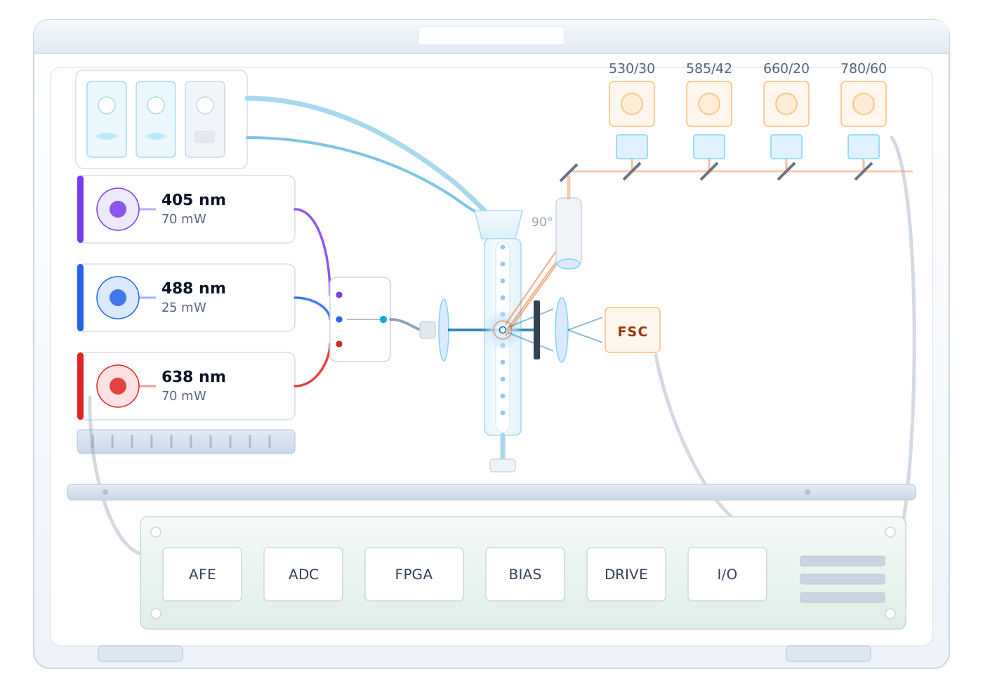
A teaching cutaway, not an assembly drawing. Lasers on the left, fluidics above them, the flow cell and its interrogation point at the centre, the filter and detector ladder to the right, the acquisition board below.
Component positions are a teaching diagram, not an assembly drawing: the placement and the exploded view are indicative. Parameter values are those of the linked specification.
Every part, parameter by parameter
The same numbers the interactive view shows, in tables you can read, search and quote.
405 nm violet laser Excitation source
Sets how many photons a violet-labelled cell can emit. What matters is not the headline power but the power that survives the fibre, whether it holds steady over a run, and where the line sits relative to the filters: a 2 nm wide line at 405 nm drifts 0.3 nm per kelvin, so case temperature moves the excitation out of the dye's absorption band long before anything in the optics moves.
| Center wavelength | 405 nm |
|---|---|
| Output power, CW | 70 mW |
| Power offered on this line | 70 mW | 80 mW |
| Spectral width (FWHM) | 2 nm typ |
| Wavelength temp. coefficient | 0.3 nm/K |
| Fiber core diameter | 3 um |
| Numerical aperture | 0.13 |
| Connector | FC/PC, SMA905, FC/APC |
| Dyes this line is chosen for | BV421, Pacific Blue, DAPI (examples) |
| Usual emission windows | 450/50 nm, 525/50 nm (examples) |
488 nm blue laser Excitation source
Sets the photon budget for every blue-excited channel at once. Because three windows share one line, the power is split between them and the dimmest dye decides the specification: the catalogue's 25 mW line is enough for a well-labelled panel, and the limit on the channel is usually the filter and the detector rather than the laser.
| Center wavelength | 488 nm |
|---|---|
| Output power, CW | 25 mW |
| Spectral width (FWHM) | 2 nm typ |
| Wavelength temp. coefficient | 0.3 nm/K |
| Fiber core diameter | 3 um |
| Numerical aperture | 0.12 |
| Connector | FC/PC, SMA905, FC/APC |
| Dyes this line is chosen for | FITC, Alexa Fluor 488, PE, PerCP (examples) |
| Usual emission windows | 530/30 nm, 585/42 nm, 695/40 nm (examples) |
638 nm red laser Excitation source
Sets how far into the far red the panel can reach. Specifications usually quote a 640 nm line; 638 nm is the line the catalogue carries and it sits inside the same absorption band, so a filter stack built for 640 nm works unchanged. What the red line does not tolerate is a dark enough detector: the 660/20 and 780/60 windows are wide, and the limit on the channel is the detector's dark current, not the excitation.
| Center wavelength | 638 nm |
|---|---|
| Output power, CW | 70 mW |
| Power offered on this line | 70 mW | 100 mW |
| Spectral width (FWHM) | 2 nm typ |
| Wavelength temp. coefficient | 0.3 nm/K |
| Fiber core diameter | 4 um |
| Numerical aperture | 0.13 |
| Connector | FC/PC, SMA905, FC/APC |
| Dyes this line is chosen for | APC, Alexa Fluor 647, APC-Cy7 (examples) |
| Usual emission windows | 660/20 nm, 780/60 nm (examples) |
Fibre delivery Optical path
Sets the spot at the interrogation point and whether the three lines are co-linear there. A single-mode pigtail's output is already defined by the fibre: core diameter and numerical aperture fix the divergence, and the launch objective turns that into a waist of the size the flow cell needs. If the three lines are not co-linear to within a few micrometres, a cell labelled for one dye sees a different excitation intensity from a cell labelled for another.
| Lines delivered | 405 / 488 / 638 nm |
|---|---|
| Fiber type | single-mode mode |
| Fiber core diameter | 3 um |
| Numerical aperture | 0.12 |
| Fiber length | 100 cm (110 cm max) |
| Connector | FC/PC, SMA905, FC/APC |
| Min. bend radius | >= 300 x fiber diameter |
| Launch | one objective shared by the three lines |
| Co-linearity at the interrogation point | set by the launch assembly you build Set by your design |
Sheath and sample fluidics Fluidics
Sets the dwell time, and the dwell time sets the photon budget. A cell crossing a 10 um spot at 1 m/s is in the beam for 10 us; double the flow rate and every event loses half its photons, which only the laser can give back. This is the coupling that decides whether a 25 mW line is enough or whether the design needs the top of the range.
| Dwell time in the beam | 10 us across a 10 um spot at 1 m/s |
|---|---|
| Core diameter at the interrogation point | set by the nozzle and the sheath-to-sample ratio Set by your design |
| Flow rate | set by the event rate you need Set by your design |
| Sample and sheath pressure | set by the fluidics you build Set by your design |
| Waste handling | set by the assay and the site Set by your design |
Flow cell Interrogation
Sets the geometry the rest of the optics is built to. The cuvette's wall thickness and surface quality decide how much excitation light is scattered into the collection path; its position fixes where the waist and the objective have to land; and it is the part that is hardest to change late, which is why the flow cell is usually chosen before the optics around it.
| Excitation lines focused into it | 405 / 488 / 638 nm |
|---|---|
| Interrogation point | one point, all three lines co-linear |
| Waist diameter | set by the launch objective Set by your design |
| Cuvette geometry and wall thickness | set by the flow cell you source Set by your design |
| Stray excitation light reaching the collection path | set by the cuvette and the beam dump Set by your design |
Collection optics Optical path
Decides which dye is seen by which detector. A bandpass filter is written as centre over width - 530/30 passes 515 to 545 nm - and the window has to sit on the dye's emission peak, never on the laser line. The dichroic that separates 405 nm from violet-triggered fluorescence is a different part from the one that separates 638 nm, which is why the excitation lines are chosen before the filter stack is laid out.
| Collection angle | 90 deg to the beam |
|---|---|
| Typical bandpass windows | 450/50, 530/30, 585/42, 695/40, 780/60 nm |
| Excitation rejection | set by the filter stack you build Set by your design |
| Dichroic split wavelengths | set by the dye panel Set by your design |
| Long-pass cut for the tandem channels | set by the tandem dyes you run Set by your design |
Detectors Detection
Gain, dark current and excess noise decide the dimmest dye the panel can carry. The catalogue's silicon APDs respond from 400 nm to 1100 nm, which spans the whole visible fluorescence band; whether one of them takes the place of a photomultiplier in a given channel is a question of photons per event, not of whether the technology fits the wavelength.
| Response spectrum | 400 - 1100 nm |
|---|---|
| Active diameter | 230 um |
| Responsivity | 80 A/W @ M=100 |
| Dark current | 0.4 nA @ M=100 |
| Optimum gain | 100 |
| Response time | 0.5 ns |
| Reverse breakdown voltage | 100 - 200 V |
| Voltage temp. coefficient | 1.1 V/C |
| Channel count | set by the dye panel Set by your design |
Signal acquisition Electronics
Sets the noise floor and the dynamic range, which together decide whether the dimmest channel in the panel is real signal or the amplifier talking. It also has to hold each detector's bias: the APD channels run at 100 - 200 V with a 1.1 V/K breakdown coefficient, so a bias loop without temperature compensation drifts the gain out from under a calibration that was set at 25 C.
| Dwell time the front end has to cover | 10 us across a 10 um spot at 1 m/s |
|---|---|
| APD bias | 100 - 200 V |
| APD bias compensation | 1.1 V/C |
| Channel count | set by the dye panel Set by your design |
| Sample rate | set by the dwell time you design for Set by your design |
| Dynamic range | set by the brightest and dimmest dye in the panel Set by your design |
Housing Mechanical
Thermal design, mostly. Three numbers decide it: the excitation lines drift 0.3 nm per kelvin, a bandpass window is tens of nanometres wide, and the APD's breakdown voltage moves 1.1 V per kelvin. Ten kelvin of case rise spends 3 nm of a 30 nm window and 11 V of a 100 - 200 V bias; neither is fatal, but both are only recoverable if the chassis makes them predictable.
| Wavelength drift of the sources | 0.3 nm/K on all three lines |
|---|---|
| Window consumed by a 10 K case rise | 3 nm of a 30 nm bandpass |
| APD bias drift | 1.1 V/K on the APD channels |
| Bench stiffness | set by the alignment you have to hold Set by your design |
| Shielding and EMC | set by the front-end noise floor Set by your design |
Every parameter value on this page is pulled from the catalogue record that renders the linked product page, so the two cannot disagree.
Parts behind these parameters
Every figure below is read from the same catalogue record that renders the product page. Nothing on this page is retyped.
The three lines this page is built on
405, 488 and 638 nm, all single-mode pigtailed and all in the same coaxial can. The dye panel decides which of them you need; the dwell time and the detector decide how much power the dimmest channel has to see.
The lines either side
A panel rarely stops at three colours. 450 nm is the shorter neighbour of the violet line, 520 nm is the nearest green to the 561 nm line most panels specify, and 660 nm reaches further into the far red than 638 nm does.
The detection side
Silicon APDs with a 400 - 1100 nm response cover the whole visible fluorescence band. Whether one of them replaces a photomultiplier in a given channel is a question of photons per event, gain and dark current - not of whether the technology fits the wavelength.
Building the filter stack
Aligning a four-colour collection path is easier with a beam you can see. These are the visible heads we keep for the bench, and the wavelengths they stand in for.
Three fibres do most of the work
Filter the catalogue by the fibre-coupled category and the three lines this page is built around come back as single-mode pigtailed modules: 405 nm for the violet dyes, 488 nm for FITC and PE, 638 nm for APC and the far-red tandems. The selector has no cytometry application yet - send us the panel of dyes you are building for and we will work back from the emission windows to the lines and the powers.
Send us the dye panel, not a part number
Every line on this page was chosen against an emission window. Tell us which dyes your panel has to resolve and we will come back with the excitation wavelengths, the powers they need and the filters they imply.