Fibre-coupled laser teardown
Anatomy of a fibre-coupled single-colour laser module
A stable single-colour fibre module is a chain of decisions: one laser diode at the ordered wavelength, the coupling optics that launch it into a small core, the pigtail and connector, a low-noise driver, the control panel and the heat path. This teardown follows the V2.0 specification, keeps its 405 - 980 nm power table separate from the catalogue line, and flags the Table 3 core-unit inconsistency for supplier confirmation.
- 1Pick a part from the bill of materials.
- 2Drop it on the module, or just click the card.
- 3Read its job, its parameters and the part numbers behind them.
Bill of materials
Every part, one optical budget. Drag a card onto the photo, or click it - the panel beside it fills in with that part's parameters.
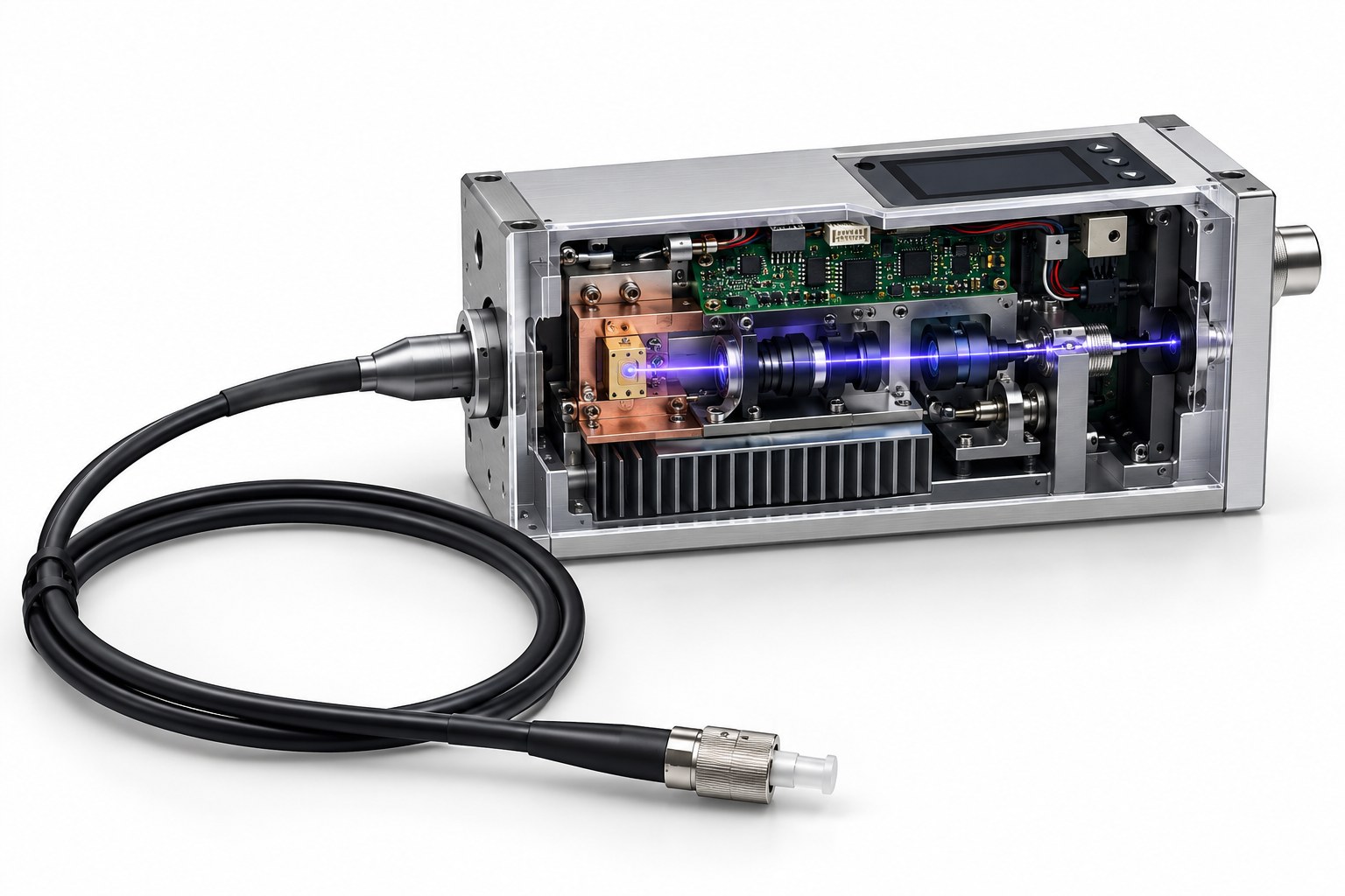
Drag a part here or click a card in the bill of materials
A teaching cutaway, not an assembly drawing. The diode and launch optics are on the left, the driver board above, the display on the top face, the heat sink below, and the fibre pigtail coils in front. The exact internal stack-up must be confirmed on the released mechanical drawing.
Component positions are a teaching diagram, not an assembly drawing: the placement and the exploded view are indicative. Parameter values are those of the linked specification.
Every part, parameter by parameter
The same numbers the interactive view shows, in tables you can read, search and quote.
Single-colour laser diode (LD) Light source
Sets the wavelength, the available optical power and the thermal load. Choose the catalogue part that matches the ordered wavelength and power, then confirm the connector and fibre type.
| Wavelength range | 405 - 980 nm (Table 3) |
|---|---|
| Output power | 20 - 100 mW (Table 3) |
| Wavelength tolerance | ±5 nm |
| Spectral width | 2 nm typ (catalogue) |
| Spatial mode | TEM00 |
| Beam quality | M² ≤ 1.2 |
Collimation and fibre-coupling optics Beam shaping
Sets coupling efficiency, output power and pointing stability. A mismatch between the diode NA and the fibre NA turns into lost power at the launch.
| Function | Collimation + coupling |
|---|---|
| Fibre core (Table 3 column) | 3 - 6.5 (unit printed as nm; confirm) Set by your design |
| Fibre spec elsewhere in V2.0 | 3.5/125 μm |
| Numerical aperture | 0.12 - 0.13 (catalogue SM) |
| Coupling efficiency | To be measured per build Set by your design |
| Coating | Wavelength-specific AR: to be specified Set by your design |
Single-mode or polarization-maintaining pigtail Delivery
Sets the delivery length, connector interface and polarization behaviour. Bend radius and connector cleanliness decide how much of the launched power reaches the experiment.
| Fibre length | 1 m |
|---|---|
| Connector options | FC/PC | FC/APC | SMA905 |
| Fibre versions | Single-mode | polarization-maintaining single-mode |
| Polarization ratio | 50:1 (V2.0) |
| Typical core/cladding | 3.5/125 μm (parameter table) |
| Minimum bend radius | To be confirmed per fibre Set by your design |
High-stability laser driver board Drive electronics
Sets output stability and noise. The <1% long-term stability and <0.2% RMS noise figures depend as much on the driver and thermal loop as on the diode.
| Input | 5.0 V DC |
|---|---|
| Recommended supply | DC 5 V / 2 A |
| Modes | CW | digital modulation |
| Long-term stability | <1% over 8 h, ±3 °C |
| RMS noise | <0.2% |
| Peak noise | <0.5% |
Display and key control assembly Control interface
Turns the module into an instrument: it exposes the setpoints, shows faults and prevents the source from being run outside its allowed window.
| Display | Panel display: type to be confirmed Set by your design |
|---|---|
| Controls | Keys / menu: to be confirmed Set by your design |
| Setpoints | Startup and maximum voltage |
| Faults | To be confirmed from firmware Set by your design |
| Interface | Standalone panel |
| Language | To be confirmed Set by your design |
Baseplate and heat sink Thermal
Keeps the diode at its specified case temperature. Wavelength drift, power droop and lifetime all move with temperature, so the heat path is part of the optical specification.
| Baseplate temperature | 50 °C |
|---|---|
| Case size | 90 × 48 × 52 mm |
| Cooling | Baseplate + heat sink |
| Operating ambient | 10 - 40 °C |
| Thermal path | LD and driver to baseplate |
| External heatsink | Recommended by V2.0 |
Metal housing and fibre interface Enclosure
Defines the mechanical envelope and the connector interface. It also sets how the module mounts, how the fibre is routed and how the heat sink is attached.
| Enclosure | 90 × 48 × 52 mm |
|---|---|
| Material | Machined aluminium: to be confirmed Set by your design |
| Fibre interface | FC/PC | FC/APC | SMA905 |
| Mounting | Baseplate holes: drawing to be confirmed Set by your design |
| Ingress protection | To be specified Set by your design |
| Label | Model, wavelength and class |
Every parameter value on this page is pulled from the catalogue record that renders the linked product page, so the two cannot disagree.
Parts behind these parameters
Every figure below is read from the same catalogue record that renders the product page. Nothing on this page is retyped.
Visible single-mode line
405 - 660 nm single-mode modules, including the 100 mW 638 nm part. These are the closest catalogue matches to the visible rows in the V2.0 table.
Near-infrared single-mode line
785 - 1064 nm single-mode modules for sensing, spectroscopy and instrument integration. The core grows from 5 to 9 um across this range.
Higher-power multimode options
When the launch has to carry watts rather than milliwatts, the family moves to 105 - 400 um multimode fibre and SMA or FC connectors.
From a free-space diode to a connectorised fibre output
The LD fixes wavelength and available power; the launch optics trade coupling efficiency against alignment tolerance; the pigtail and connector carry the light to the instrument; the driver holds current and noise; the baseplate holds the diode case temperature. The V2.0 table covers 405 - 980 nm at 20 - 100 mW, while the catalogue family covers 405 - 1064 nm at up to 3 W in multimode fibre. Use the table for the application target and the catalogue record for the part that ships.
Send the wavelength, power and connector
Tell us the ordered wavelength, output power at the fibre, core and connector, and whether the version must maintain polarization. We will match the catalogue module and confirm the V2.0 table rows that still need supplier clarification.