Er,Yb:glass microchip laser teardown
Inside a 1535 nm passively Q-switched erbium glass laser
A 1535 nm erbium glass transmitter converts a short 940 nm pump pulse into an eye-safe 1535 nm output inside a bonded microchip cavity. This teardown follows the eight mechanical, pump, thermal, gain, Q-switch, coating, window and electrical parts in the supplied exploded view, then maps the result to the current LZ1535 transmitter and power-module catalogue.
- 1Pick a part from the bill of materials.
- 2Drop it on the module, or just click the card.
- 3Read its job, its parameters and the part numbers behind them.
Bill of materials
Every part, one optical budget. Drag a card onto the photo, or click it - the panel beside it fills in with that part's parameters.
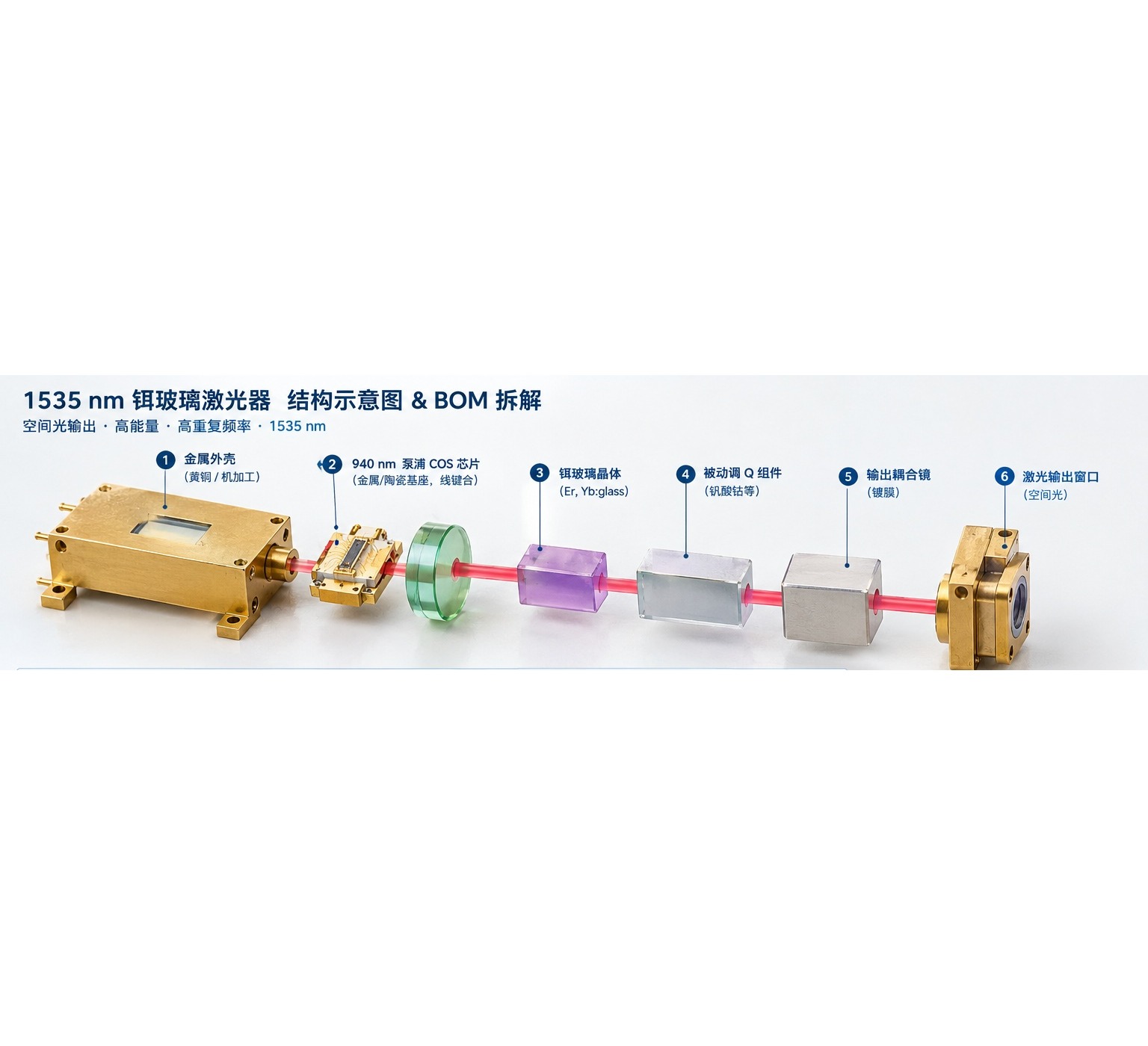
Drag a part here or click a card in the bill of materials
Exploded teaching view, not an assembly drawing. The pump, heat sink, gain medium and cavity optics are drawn left to right; the free-space output has no fibre pigtail.
Component positions are a teaching diagram, not an assembly drawing: the placement and the exploded view are indicative. Parameter values are those of the linked specification.
Every part, parameter by parameter
The same numbers the interactive view shows, in tables you can read, search and quote.
Metal housing and end caps Mechanical
Defines the optical-axis height, end-cap interfaces, sealing and the thermal path to the host. Outer diameter and mounting geometry change with the 14.4, 21, 25 and 40 mm catalogue envelopes.
| Function | Housing and optical datum |
|---|---|
| Typical envelope | 14.4 - 40 mm diameter (catalogue) |
| Material | Metal alloy, to be specified Set by your design |
| Sealing | Application-specific Set by your design |
940 nm pump COS Light source
Delivers the absorbed 940 nm pump power that excites the Er,Yb:glass. Peak current, emitter width, fast- and slow-axis divergence and thermal resistance must match the selected energy class.
| Center wavelength | 940 nm |
|---|---|
| Package | COS |
| Peak pump power | Set by energy class Set by your design |
| Emitter geometry | To be confirmed per COS Set by your design |
Copper heat sink and locating mount Thermal
Keeps the pump die and crystal at a stable temperature and preserves their alignment. The thermal design must use the real pump waveform and average power, not the laser output energy alone.
| Material | Copper alloy |
|---|---|
| Contact surface | Flatness and finish to be specified Set by your design |
| Thermal resistance | Depends on pump duty Set by your design |
| Alignment | Sets COS-to-crystal height |
Er,Yb:glass gain medium Gain medium
Stores the pump energy and emits around 1535 nm. The crystal and saturable absorber are usually a bonded stack, so the supplier's delivery boundary decides whether they are separate BOM lines.
| Laser wavelength | 1535 nm |
|---|---|
| Pump absorption band | 940 nm |
| Doping and thickness | Per energy class Set by your design |
| End-face finish | Polish and coating to be specified Set by your design |
Passive Q-switch assembly Q-switch
Sets pulse build-up, pulse width and repetition behaviour. Initial transmission, absorption cross-section, damage threshold and thermal stability must match the gain medium.
| Type | Passive saturable absorber |
|---|---|
| Material | Co:spinel class, to be confirmed Set by your design |
| Pulse width | 4 - 8 ns in catalogue families |
| Integration | Bonded or separate Set by your design |
Output coupler and cavity coating Cavity optic
Sets feedback, threshold and output coupling. Reflectivity at 1535 nm and transmission at the 940 nm pump must be specified together with damage threshold.
| Reflectivity at 1535 nm | Design-specific Set by your design |
|---|---|
| Transmission at 940 nm | Design-specific Set by your design |
| Coating | Dielectric multilayer |
| Damage threshold | To be confirmed Set by your design |
Laser output window Optical interface
Passes the 1535 nm beam without a fibre connector. The LZ1535 catalogue family is a free-space transmitter line; do not assume a fibre-coupled output.
| Output | Free-space beam |
|---|---|
| Window material | To be confirmed Set by your design |
| Coating | AR at 1535 nm Set by your design |
| Connector | None |
Retaining ring, locator and electrical pins Electrical interface
Maintains preload and alignment while carrying pump current. Pin polarity, spacing, insulation and solder process must follow the COS and housing drawings.
| Function | Clamp, locate and connect |
|---|---|
| Pin count | Per COS package Set by your design |
| Polarity | Per device drawing Set by your design |
| Driver | External LZ1535-PS module |
Every parameter value on this page is pulled from the catalogue record that renders the linked product page, so the two cannot disagree.
Parts behind these parameters
Every figure below is read from the same catalogue record that renders the product page. Nothing on this page is retyped.
Compact 100 - 300 uJ transmitters
Four 10 Hz, 4 ns transmitters cover the 14.4, 21 and 25 mm envelopes. The 10 A power module states a 200 uJ maximum, so the 300 uJ transmitter is not automatically covered by that pairing.
1 mJ long-range transmitter
The 40 mm transmitter is the catalogue path to a 1 mJ class pulse. The 30 A power module states a 1 mJ class range and 1 / 5 / 10 Hz switching, which matches this transmitter's 10 Hz rating.
1 kHz high-repetition transmitter
The 1 kHz model fits scanning and short-range LiDAR where many pulses matter more than the largest single-pulse energy. No catalogue LZ1535-PS driver is listed at 1 kHz; the two PS modules switch at 1 / 5 / 10 Hz only.
Power and control modules
The two LZ1535-PS modules set current, repetition rate and pulse width digitally. Check the published energy range and the 1 / 5 / 10 Hz switching limit before pairing either module with a transmitter.
From a 940 nm pump pulse to a 1535 nm eye-safe output
The 940 nm COS pumps the Er,Yb:glass gain medium; the saturable absorber Q-switches the cavity; the output coupler sets feedback and extraction; the window protects the free-space aperture. The catalogue side starts at the integrated LZ1535 transmitter, so the internal stack in this drawing is a design reference, not a set of stocked loose parts. Pulse energy, repetition rate and pulse width are taken from the current product pages.
Match energy, repetition rate and drive current
Send the target pulse energy, repetition rate, pulse width, beam divergence and available supply. We will match one of the six LZ1535 transmitters and the 10 A or 30 A power module without extrapolating beyond the published ratings.