Confocal microscopy teardown
Anatomy of a multi-wavelength confocal microscope
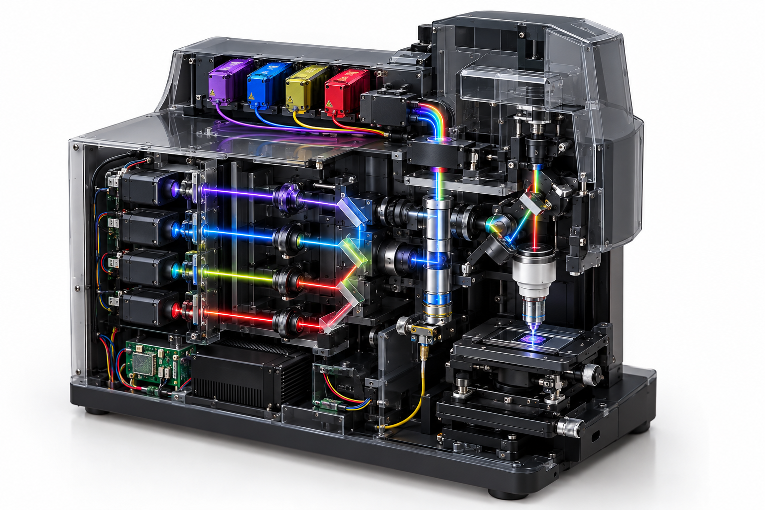
Four fibre-coupled excitation lines are combined into one beam, scanned across the sample, collected through the objective and separated again by wavelength before detection. The source drawing specifies a 640 nm red line; this teardown maps it to the catalogue's 638 nm family and links every excitation channel to a real fibre-coupled part.
- 1Pick a part from the bill of materials.
- 2Drop it on the module, or just click the card.
- 3Read its job, its parameters and the part numbers behind them.
Bill of materials
Every part, one optical budget. Drag a card onto the photo, or click it - the panel beside it fills in with that part's parameters.
Drag a part here or click a card in the bill of materials
Teaching cutaway, not an assembly drawing. The excitation bank and wavelength combiner are at the upper left; the sample, objective and scanning optics occupy the centre; the detector path and control electronics surround them.
Component positions are a teaching diagram, not an assembly drawing: the placement and the exploded view are indicative. Parameter values are those of the linked specification.
Every part, parameter by parameter
The same numbers the interactive view shows, in tables you can read, search and quote.
405 nm violet fibre-coupled laser Excitation source
Sets the short-wavelength end of the excitation engine and the photon budget for violet dyes.
| Center wavelength | 405 nm |
|---|---|
| Output power, CW | 80 mW |
| Fiber core diameter | 3 um |
| Numerical aperture | 0.13 |
| Connector | FC/PC, SMA905, FC/APC |
| Wavelength temp. coefficient | 0.3 nm/K |
488 nm blue fibre-coupled laser Excitation source
Provides the 488 nm excitation band and must be matched to the emission filters behind the sample.
| Center wavelength | 488 nm |
|---|---|
| Output power, CW | 25 mW |
| Fiber core diameter | 3 um |
| Numerical aperture | 0.12 |
| Connector | FC/PC, SMA905, FC/APC |
520 nm green replacement for the 561 nm channel Excitation source
This substitution is not wavelength-equivalent. Confirm the fluorophore excitation spectrum and every downstream dichroic/filter before use.
| Center wavelength | 520 nm |
|---|---|
| Output power, CW | 50 mW |
| Original drawing wavelength | 561 nm |
| Catalogue substitution | 520 nm Set by your design |
| Fiber core diameter | 3 um |
| Connector | FC/PC, SMA905, FC/APC |
638 nm red fibre-coupled laser Excitation source
Provides the red excitation line; confirm the fluorophore and emission filter passbands against 638 nm rather than 640 nm.
| Center wavelength | 638 nm |
|---|---|
| Output power, CW | 100 mW |
| Drawing label | 640 nm |
| Catalogue wavelength | 638 nm |
| Fiber core diameter | 4 um |
| Connector | FC/PC, SMA905, FC/APC |
Beam delivery: WDM, collimator and fold mirrors Beam delivery
Insertion loss, channel isolation and output geometry set the available power and beam quality.
| Input channels | 4 |
|---|---|
| Wavelength set | 405 / 488 / 520 / 638 nm |
| Insertion loss | Define with supplier Set by your design |
Dichroic, filter and collection optics Optical / control subsystem
Separates excitation from emission and collects each band into its detector channel.
| Selection basis | Set by the complete optical design Set by your design |
|---|
Detection fibre and multi-channel detector bank Optical / control subsystem
Carries collected fluorescence to the multi-channel detector bank.
| Selection basis | Set by the complete optical design Set by your design |
|---|
Galvo, scan lens and tube lens Optical / control subsystem
Scans the excitation spot and relays it into the objective pupil.
| Selection basis | Set by the complete optical design Set by your design |
|---|
Objective and sample stage Optical / control subsystem
Focuses excitation into the sample and collects the return light; the stage positions the sample.
| Selection basis | Set by the complete optical design Set by your design |
|---|
Control and data-acquisition system Optical / control subsystem
Synchronises lasers, scanner and detector readout.
| Selection basis | Set by the complete optical design Set by your design |
|---|
Every parameter value on this page is pulled from the catalogue record that renders the linked product page, so the two cannot disagree.
Parts behind these parameters
Every figure below is read from the same catalogue record that renders the product page. Nothing on this page is retyped.
405 and 488 nm excitation
Direct catalogue matches for the violet and blue fibre-coupled lines.
561 to 520 nm substitution
No 561 nm part exists in the catalogue. The 520 nm line is the nearest listed source and requires spectral validation.
640 to 638 nm mapping
The drawing's red channel is represented by the two catalogue 638 nm fibre-coupled parts.
Four source channels, two deliberate wavelength substitutions
405 nm, 488 nm and the 638 nm red replacement map directly to fibre-coupled catalogue products. The 561 nm line has no catalogue equivalent, so the page shows the 520 nm module as the nearest available source and flags the dye/filter review that must happen before substitution. The source drawing's 640 nm label is standardised to our 638 nm product family.
Send the excitation and emission bands
Tell us the laser lines, dye or fluorophore set, power at the sample and detector channels. We will map the excitation side to catalogue fibre-coupled modules and identify the filters still required.