Optogenetics light-delivery teardown
Anatomy of a fibre-coupled optogenetics laser
Optogenetics uses light to control cells that have been genetically modified to express light-sensitive proteins such as channelrhodopsins, halorhodopsins or red-shifted opsins. The laser does not create the response by itself: the opsin sets the usable wavelength, the irradiance at the tissue sets activation strength, pulse width and repetition set timing, and the fibre delivers all of it to the target region. This teardown separates the source, combining, modulation, control, fibre-output and implantable interfaces, and maps the requested wavelengths to the closest fibre-coupled catalogue products.
- 1Pick a part from the bill of materials.
- 2Drop it on the module, or just click the card.
- 3Read its job, its parameters and the part numbers behind them.
Bill of materials
Every part, one optical budget. Drag a card onto the photo, or click it - the panel beside it fills in with that part's parameters.
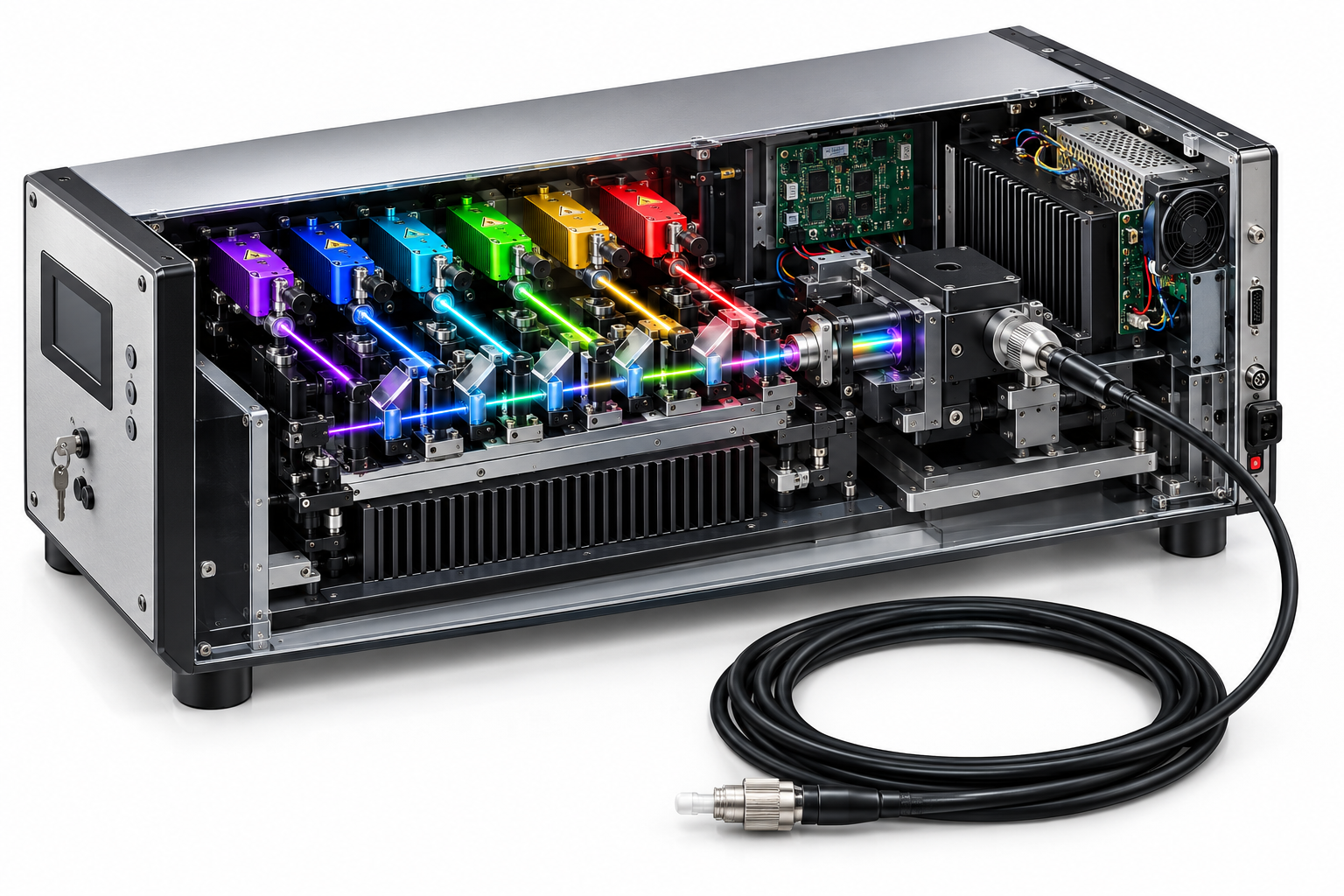
Drag a part here or click a card in the bill of materials
Teaching cutaway, not an assembly drawing. Sources and beam-conditioning optics lead to a modulated fibre output; the driver, thermal path and implantable ferrule define what reaches the tissue.
Component positions are a teaching diagram, not an assembly drawing: the placement and the exploded view are indicative. Parameter values are those of the linked specification.
Every part, parameter by parameter
The same numbers the interactive view shows, in tables you can read, search and quote.
Fibre-coupled laser source bank Excitation source
Wavelength must match the opsin action spectrum. Power at the source is only the starting point; irradiance at the tissue after fibre and implant losses is what drives activation.
| Center wavelength | 405 nm |
|---|---|
| Output power, CW | 80 mW |
| 473 nm catalogue substitute | 488 nm Set by your design |
| 589/594 and 635/640 nm substitute | 638 nm Set by your design |
| Fiber core diameter | 3 um |
| Connector | FC/PC, SMA905, FC/APC |
Fibre collimator and coupling optics Beam conditioning
Coupling efficiency and fibre NA determine how much of the source reaches the implant.
| Function | Collimation / coupling / axis matching |
|---|---|
| Fibre interface | Selected by configuration Set by your design |
| Key calibration | Coupling efficiency, axis and return loss |
Dichroic combiner for dual wavelengths Beam combining
Coating edges, incidence angle and isolation must match the selected wavelengths.
| Inputs | 2 |
|---|---|
| Coating band | Set by wavelength pair Set by your design |
AOM or mechanical shutter Modulation
Rise/fall time, extinction ratio and jitter directly change the stimulation protocol.
| Option | AOM or mechanical shutter |
|---|---|
| Rise / fall time | Depends on configuration Set by your design |
Driver and waveform controller Control electronics
Closed-loop power, trigger latency and waveform resolution determine repeatability of the stimulus.
| Power step | 0.1 mW example |
|---|---|
| Waveform time | 1 ms-3600 s / DC example |
| Interfaces | BNC sync/trigger; USB example |
Fibre output connector and patch cable Fibre delivery
Core diameter and NA determine the achievable spot and coupling loss; bends and connectors add loss and modal noise.
| Connector | SMA905 / FC options Set by your design |
|---|---|
| Fibre length | Set by bench and animal geometry Set by your design |
Thermal path and power module Thermal / power
Thermal drift changes wavelength and power; pulsed protocols also create average-power heating.
| Cooling | Model dependent Set by your design |
|---|---|
| Supply | Model dependent Set by your design |
Implantable ferrule and fibre tip Implant interface
Tip geometry, insertion depth and fibre numerical aperture determine the illuminated volume and local heating.
| Tip / ferrule | Set by animal and brain region Set by your design |
|---|---|
| Sterilisation | Follow laboratory protocol Set by your design |
Housing, interlocks and status indication Safety / enclosure
The finished instrument, fibre and implant determine the safety class; the bare diode does not.
| Interlock | Model dependent Set by your design |
|---|---|
| Safety class | Assess complete instrument Set by your design |
Every parameter value on this page is pulled from the catalogue record that renders the linked product page, so the two cannot disagree.
Parts behind these parameters
Every figure below is read from the same catalogue record that renders the product page. Nothing on this page is retyped.
Visible optogenetics channels
Direct or nearest catalogue fibre-coupled products for violet, blue, green and red excitation.
Near-infrared fibre-coupled options
Catalogue lines for red-shifted or NIR-compatible protocols; opsin and tissue penetration must be checked individually.
What optogenetics adds to a laser selection
Opsins respond over characteristic bands: blue channelrhodopsins are commonly used near 470 nm, yellow/red-shifted inhibitory or red-activatable proteins near 590-640 nm, and some actuators or indicators extend into the near infrared. Efficacy depends on irradiance at the tissue, not laser power at the connector. Fibre core, NA, bending, connector loss and the implantable ferrule set the delivered power; pulse width, repetition rate and duty cycle set temporal precision and heat. A 473 nm request is mapped here to 488 nm, 589/594 nm to 638 nm and 635/640 nm to 638 nm only as catalogue substitutions: the opsin spectrum and safety review must be repeated for the changed wavelength.
Send the opsin, target region and stimulation protocol
Tell us the opsin, required irradiance, pulse train, fibre type, implant geometry and working distance. We will map the excitation to a fibre-coupled source and the loss budget through connector, fibre and ferrule.