LiDAR teardown
Anatomy of a spinning LiDAR
A LiDAR is a ranging chain mounted on a rotor. The emitter, the detector, the optics between them and the electronics that time the round trip all go round once per revolution behind a window, and the angle the beam came back at is half the measurement: the round trip gives the distance, the encoder gives the bearing, and the two of them are one point. Pick a part from the bill of materials and drop it on the scanner; every parameter comes with the catalogue parts that carry it.
- 1Wählen Sie ein Teil aus der Stückliste.
- 2Ziehen Sie es auf das Modul oder klicken Sie einfach die Karte an.
- 3Lesen Sie seine Aufgabe, seine Parameter und die Bestellnummern dahinter.
Stückliste
Jedes Teil, ein optisches Budget. Ziehen Sie eine Karte auf das Foto oder klicken Sie sie an - das Feld daneben füllt sich mit den Parametern dieses Teils.
Teil hierher ziehen oder eine Karte in der Stückliste anklicken
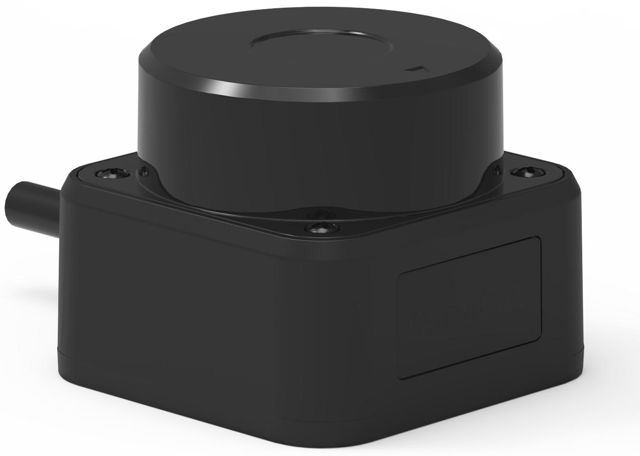
A spinning 2D LiDAR, three-quarter view. The turret on top carries the transmit and receive optics and turns behind the window band around its lower rim; the base below holds the boards, the supply and the connector.
Die Positionen der Komponenten sind ein Lehrschema, keine Montagezeichnung: Anordnung und Explosionsdarstellung sind Richtwerte. Parameterwerte sind die der verlinkten Spezifikation.
Jedes Teil, Parameter für Parameter
Dieselben Zahlen wie in der interaktiven Ansicht, in Tabellen, die Sie lesen, durchsuchen und zitieren können.
905 nm laser diode Transmitter
Emits the ranging pulse for every point in the scan. On a scanner the constraint is not the diode's peak power on its own but the duty cycle it can hold at the point rate you need: the catalogue's 905 nm parts are specified to 0.1 % duty and 10 kHz, so a scanner that wants more points has to spend pulse width, not ask the diode for more peak power.
| Peak wavelength | 905 nm (895 - 915 nm) |
|---|---|
| Peak output power | 25 - 300 W |
| Pulse energy @ 100 ns | 2.5 - 30 uJ |
| Beam divergence, parallel | 9 deg |
| Beam divergence, perpendicular | 25 deg |
| Pulse width | 1 - 100 ns (max 100 ns) |
| Duty cycle, max | 0.1 % |
| Repetition rate | up to 10 kHz |
| Package | TO56 | bare die | VCSEL array | metal stack |
| Est. range, retro-reflective (100 W) | 1.2 km |
| Est. range, diffuse target (100 W) | 400 m |
Avalanche photodiode Receiver
Detects the returning pulse at every angle of the sweep. A small active area keeps capacitance and dark current down, which is what makes a sharp timing edge; it also shrinks the receive aperture, which is the trade against range. Where a scan is built from several beams at once, the catalogue's 16-element linear array carries one channel per beam instead of one detector for the whole sweep.
| Response spectrum | 400 - 1100 nm |
|---|---|
| Wavelength | 905 nm |
| Active area | 16 elements |
| Responsivity | 80 A/W @ M=100 |
| Response time | 0.5 ns |
| Dark current | 0.4 nA @ M=100 |
| Total capacitance | 1.0 pF @ M=100 |
| Optimum gain | 100 |
| Reverse breakdown voltage | 100 - 200 V |
| Voltage temp. coefficient | 1.1 V/C |
| Active area, single channel | 230 um | 500 um |
| Package | TO-46 | LCC1 ceramic | LCC2 ceramic | linear array |
Exit window and transmit / receive optics Optical path
It decides the spot the beam makes on the target and the cone of light the receiver can accept. A fast-axis collimator takes the 25 degree vertical fan down to 6 degrees, which is what keeps the returning light inside a small receive aperture a few metres out; the receive field then has to be wide enough to swallow the boresight error the rotor introduces over temperature.
| Vertical divergence, collimated | 6 deg |
|---|---|
| Horizontal divergence, bare | 9 deg |
| Receive filter | 905 nm band-pass |
| Detector response window | 400 - 1100 nm |
| Receive aperture | Set by your design Von Ihrem Entwurf festgelegt |
| Transmission, transmit and receive path | Set by your design Von Ihrem Entwurf festgelegt |
| Window material and coating | Set by your design Von Ihrem Entwurf festgelegt |
| Boresight tolerance | Set by your design Von Ihrem Entwurf festgelegt |
Rotor, motor and encoder Scan mechanism
It sets the angular resolution and the point rate. A point needs the round trip to be over before the beam has moved further than the spot, so the faster the rotation, the shorter the pulse the geometry allows - which is why the scan mechanism, not the diode, is usually what limits a 2D scanner's range.
| Scan architecture | Rotating head, polygon mirror, MEMS or OPA - set by your design Von Ihrem Entwurf festgelegt |
|---|---|
| Rotation speed | 5 - 20 Hz typical for a 2D head Von Ihrem Entwurf festgelegt |
| Angular resolution | 0.25 - 1 deg, set by your design Von Ihrem Entwurf festgelegt |
| Points per revolution | Set by your design Von Ihrem Entwurf festgelegt |
| Repetition rate available per beam | 1 kHz - 30 kHz adjustable |
| Motor drive | Brushless DC with encoder feedback Von Ihrem Entwurf festgelegt |
| Bearing life | Set by your design - the rotor is the only moving part Von Ihrem Entwurf festgelegt |
Timing and signal-processing board Electronics
It turns an optical round trip into a number and an angle into a coordinate. The driver's peak current, pulse width, rise time and trigger arrangement have to match the diode; the timing chain then has to find the same edge in a return thousands of times weaker than the outgoing pulse, once for every point in the sweep.
| Peak pulse current | 70 A |
|---|---|
| Pulse width | 50 ns - 1 us adjustable |
| Repetition rate | 1 kHz - 30 kHz adjustable |
| Rise time | 7.5 ns typical |
| Fall time | 12 ns typical |
| Control interface | Internal trigger / external TTL |
| Laser drive voltage | 1 - 50 V DC |
| Time-to-digital converter | Set by your design - the timing resolution is what limits the distance resolution Von Ihrem Entwurf festgelegt |
| Host interface | UART | Ethernet | USB - set by your design Von Ihrem Entwurf festgelegt |
Power and detector bias Power
Avalanche gain moves with temperature at about 1.1 - 1.4 V per degree, so the bias supply is what keeps the receiver's gain - and its timing - constant from a cold start to a warm housing. Noise on the laser rail shows up as pulse-to-pulse energy jitter, and jitter is range error.
| Supply voltage | 12 V DC |
|---|---|
| Laser drive voltage | 1 - 50 V DC |
| MOSFET drain-source voltage | 80 V |
| Gate threshold voltage | 2 - 4 V |
| Bias rail for the detector | 100 - 200 V |
| Bias drift with temperature | 1.1 V/C |
| Logic rails | Set by your design Von Ihrem Entwurf festgelegt |
| Average power draw | Set by your design - the point rate decides it Von Ihrem Entwurf festgelegt |
| Ripple and noise | Set by your design Von Ihrem Entwurf festgelegt |
Shell, optical bench and interface Mechanical
It keeps the optical axis where the calibration left it, over temperature, over vibration and over the life of the bearing. Every mechanical tolerance between the emitter, the collimator and the detector turns into a boresight error at the far end of the range, which is why the bench and the shell are read together with the optics rather than as an enclosure.
| Operating temperature, detector-rated | -40 to +85 C |
|---|---|
| Storage temperature, detector-rated | -55 to +125 C |
| Optical bench material | Set by your design - thermal expansion is a boresight term Von Ihrem Entwurf festgelegt |
| Window material and hardness | Set by your design Von Ihrem Entwurf festgelegt |
| Ingress protection | Set by your design - must be verified against the rating claimed Von Ihrem Entwurf festgelegt |
| Mounting datum | Set by your design Von Ihrem Entwurf festgelegt |
| Connector and interface | Set by your design Von Ihrem Entwurf festgelegt |
Jeder Parameterwert auf dieser Seite stammt aus dem Katalogeintrag, der die verlinkte Produktseite erzeugt, sodass die beiden nicht widersprechen können.
Bauteile hinter diesen Parametern
Jede Zahl unten kommt aus demselben Katalogeintrag, der die Produktseite erzeugt. Hier ist nichts neu abgetippt.
905 nm transmit chain for a scanner
A 2D scanner wants the middle of the family, not the top: enough energy per pulse to see a wall tens of metres out, at a point rate and a duty cycle the diode can hold for a whole shift.
Package the emitter yourself: bare die
A sealed scanning head is often built around a die rather than a can, so that the bench can be machined around the emitting area the design actually needs - and so that there is no lens barrel in the way.
Or go surface-emitting
A VCSEL array is lower, has a rounder spot and no fast-axis collimator to align, at the cost of peak power: it suits a short, dense scan rather than a long-range one, and it is cheaper to mount on a bench.
Receive chain: one detector or an array
The smallest active area that still collects the return gives the sharpest edge; an array trades that for one channel per beam. The 1550 nm part is here for the design that goes eye-safe instead.
Drive and timing
One board carries the pulse generator and the driver. Its repetition rate is the ceiling on the point rate of every beam in the scan, and its rise time is the floor under the timing resolution.
Alignment and aiming optics
Boresighting a scanner is easier with a beam you can see: the transmit spot and the receive field are lined up on the build bench against a collimated visible head, and checked again through the window band at the end of the line.
What changes when the beam has to sweep
A range-only product can fire as often as its battery allows. A scanner cannot: it has a fixed number of shots per revolution, so a shorter pulse and a lower duty cycle buy either more points or more reach, never both. That trade - points per second against range per point - is what every part on this page is chosen against.
The receive side sets the point budget
Send us the points per second and the range you need and we will work back through the budget - receive aperture, detector area, filter, and the pulse the diode has to deliver to close it.