












Engineering comparison · 905 nm pulsed laser diode
PLD905-140W-M 140 W vs OSRAM SPL UL90AT08 120 W
A datasheet-based comparison of two 905 nm pulsed laser diodes. The important differences extend beyond nominal peak power to drive voltage, epitaxial stack, aperture, reverse-voltage limits and package variants.
Product A · Leirte
PLD905-140W-M series
4 epitaxial stacked emitters
Product B · OSRAM
SPL UL90AT08
3 epitaxial stacked emitters
Updated 2026-10-30 · 10 min read
The two devices are both 905 nm, TO56-family pulsed laser diodes, but their nominal power, stack count, operating voltage and reverse-voltage limits differ substantially.
This article keeps datasheet values, nominal product ratings and typical characteristics separate. “Not listed” means the supplied document did not provide the data; it is not evidence of poor performance.
Core differences at a glance
The most consequential values for a system design are below. Test conditions and parameter definitions matter as much as the headline number.
Nominal peak power
Product/ordering rating. This is not a guarantee that every sample differs by exactly 20 W under all conditions.
Epitaxial emitters
Stack count alone does not establish efficiency, reliability or beam quality.
Typical operating voltage
The driver, switch voltage rating, supply architecture and parasitics must be re-evaluated.
Emitter aperture
The short dimension differs and can change collimation, focusing and spot shaping.
Complete specification comparison
The table separates nominal ratings, typical characteristics and absolute maximum ratings.
| Parameter | PLD905-140W-M series | SPL UL90AT08 | Engineering reading |
|---|---|---|---|
| Wavelength | 905 nm · 895–915 nm | 905 nm · 895–915 nm | Values agree; actual spectrum still needs measurement. |
| Nominal peak power | 140 W | 120 W | Nominal power tiers differ; do not infer a fixed measured ratio. |
| Characteristic peak output | 124 W min · 144 W typ | 125 W typ | Typical and nominal definitions differ; purchase limits must be agreed. |
| Forward current / test current | Iop 33 A min · 40 A typ | IF 40 A test condition | Typical and nominal definitions differ; purchase limits must be agreed. |
| Operating voltage | 19.6 V min · 22 V typ | 11 V typ | Electrical limits differ; the replacement is not pin-power equivalent. |
| Threshold current | 0.5 A min · 0.75 A typ · 1 A max | 0.6 A typ | Typical and nominal definitions differ; purchase limits must be agreed. |
| Spectral width (FWHM) | 7 nm typ | 7 nm typ | Values agree; actual spectrum still needs measurement. |
| Wavelength temperature coefficient | 0.28 nm/K typ | Not listed | Driver voltage, current, edges and ringing must be measured at the device. |
| Emitter / epitaxial stack count | 4 emitters | 3 emitters | Nominal power tiers differ; do not infer a fixed measured ratio. |
| Emitter aperture | 220 × 18 µm | 220 × 10 µm | Optical geometry needs fresh optimization and measurement. |
| Divergence parallel to pn junction | 9° typ · 10° max | 10° typ | Values agree; actual spectrum still needs measurement. |
| Divergence perpendicular to pn junction | 25° typ · 28° max | 25° typ | Values agree; actual spectrum still needs measurement. |
| Maximum pulse width | 100 ns | 100 ns | Values agree; actual spectrum still needs measurement. |
| Maximum duty cycle | 0.1% | 0.1% | Values agree; actual spectrum still needs measurement. |
| Maximum reverse voltage | 20 V | 3 V | Electrical limits differ; the replacement is not pin-power equivalent. |
| Temperature and soldering ratings | Operating −40…+85 °C · storage −40…+100 °C · solder 260 °C max | Same ratings | Values agree; actual spectrum still needs measurement. |
| Thermal resistance, junction to solder | Not listed | 25 K/W typ junction-to-solder | Driver voltage, current, edges and ringing must be measured at the device. |
| Package / pin options | TO56 · 3-pin, 2.0 mm and 2.54 mm variants | Metal Can TO56 · 3-pin | TO56 does not guarantee mechanical or electrical interchangeability. |
| Ordering information | PLD905-140W-M / -M-2.0 / -MP / -M/Z | SPL UL90AT08 · Q65112A2621 | Nominal power tiers differ; do not infer a fixed measured ratio. |
Typical values are not per-unit guarantees. The comparison preserves the supplied definitions and does not back-calculate missing data.
How the optical and electrical differences affect the system
Datasheet parameters must be translated into driver, transmit optics, receiver, thermal and algorithm requirements.
PLD905-140W-M series
Higher nominal power tier and higher typical operating voltage
- Nominal 140 W; characteristic table: 144 W typical and 124 W minimum under its stated test conditions.
- Typical operating voltage 22 V and operating current 40 A typical; verify driver voltage headroom, pulse edges and current control.
- Emitter aperture 220 × 18 µm; refit collimation and focusing using the actual near field.
- Maximum reverse voltage 20 V, but reverse stress should still be avoided during hot-plug, ringing and turn-off.
- The ordering table lists several pin variants; choose the exact suffix rather than ordering only by the base model.
OSRAM SPL UL90AT08
120 W nominal tier and lower typical operating voltage
- Nominal 120 W; characteristic typical 125 W at IF = 40 A, 100 ns, D = 0.01% and 25 °C.
- Typical operating voltage 11 V; an existing driver built around this part must be re-evaluated before using a higher-voltage device.
- Emitter aperture 220 × 10 µm; collimation, focusing and energy distribution still require actual near/far-field data.
- Maximum reverse voltage 3 V. Continuous reverse operation is prohibited; avoid reverse bias and transient overshoot.
- Typical junction-to-solder thermal resistance is 25 K/W under the stated mounting condition; this is not complete module thermal resistance.
Application directions and their limits
Application tags are taken from the supplied datasheets. A listed direction does not mean the complete product is certified.
PLD listed
Handheld laser rangefinders
Golf, hunting and construction distance measurement. Peak power contributes to the echo budget, but does not determine range alone.
PLD listed
UAV ranging and obstacle avoidance
Evaluate transmit field, scanning, receiver sensitivity, sunlight and target reflectance, plus thermal and vibration tests.
Both
Professional laser sensors / LiDAR
PLD lists professional sensors and OSRAM lists LiDAR. Scanning architecture, receive optics and repetition rate still need matching.
OSRAM listed
3D sensing and CCTV
OSRAM lists 3D sensing, CCTV surveillance and electronic equipment. Validate eye-safety strategy, exposure synchronization and image-system compatibility.
OSRAM listed
Industrial automation and light curtains
OSRAM lists machine control, light curtains, vision control and measurement/leveling. Long-term stability and target motion still matter.
OSRAM direction only
Automotive LiDAR / ACC / Pre-Crash
Important limit: OSRAM lists LiDAR, Pre-Crash and ACC but also states “Not released for automotive applications.” Do not treat this as automotive qualification.
How to make a fair selection decision
Do not rank by brand or power alone. Identify which candidate should be validated against the actual system constraints.
Evaluate PLD905-140W-M first when…
The project needs to assess the 140 W nominal tier and a four-stack emitter.
- Higher nominal peak power is a meaningful candidate for the transmit budget.
- The driver can support about 22 V typical and 40 A with transient margin.
- The team wants to evaluate a 220 × 18 µm aperture and its beam-shaping consequences.
- A specific pin suffix, electrical transients, thermal path, lifetime and laser safety can be fully validated.
Data still to request: thermal resistance, full-temperature output, batch distribution and exact mechanical drawings.
Keep or evaluate SPL UL90AT08 when…
The existing design is built around the 120 W tier and lower-voltage device.
- The module, driver and PCB already match its 11 V typical and 40 A test condition.
- The performance target is adequately met by the 120 W nominal tier.
- Its listed thermal resistance can serve as a starting point for comparison.
- The application is within its listed sensing, CCTV, industrial or measurement directions and respects the automotive restriction.
The supplied OSRAM datasheet is Version 1.3 dated 2019-07-03; confirm current product status before production.
Conclusions these datasheets do not support
| Common shortcut | Why the evidence is insufficient | Fair validation |
|---|---|---|
| 140 W must reach 16.7% farther than 120 W | Range is nonlinear and depends on target, optics, receiver, pulse and algorithm. | Fix target, environment, optics, pulse and receiver; compare detection rate, error and false alarms. |
| Lower voltage must mean higher efficiency | Voltage alone does not define wall-plug efficiency. | Measure electrical input and optical output at the same junction temperature, pulse and current. |
| A narrower aperture must couple more easily | Divergence, near field, lens NA, aberrations and tolerances also matter. | Optimize the same optical architecture for both and record coupling, spot and yield. |
| Both are TO56, so they are drop-in replacements | Pins, flange, case potential and emitter position can differ. | Compare drawings, pin definitions, grounding and PCB pads; build sample assemblies. |
| Missing thermal or wavelength data must be worse | Missing data is not zero or poor performance. | Request equivalent supplier data or run an agreed measurement. |
Sample and replacement validation checklist
Put both parts under the same test plan instead of comparing typical curves from different conditions.
Measure voltage, current, edges, overshoot and ringing at the device pins.
Use identical FWHM, repetition rate, duty cycle and trigger; check average power limits.
Calibrate detector bandwidth and responsivity; record multiple units and batches.
Scan center wavelength and spectral width across current and target temperature.
Measure both axes, spot shape and energy distribution; evaluate the lensed spot.
Check turn-off, cables, ESD and connection events; protect to the selected device rating.
Use the same pad, heatsink, solder process and measurement point; record steady and transient rise.
Verify suffix, pin positions, case potential, flange, emitter position and assembly stress.
Test reflectivity, distance, angle, ambient light and temperature; record detection, error and false alarms.
Define aging, thermal cycling, vibration, batch consistency and failure criteria.
FAQ and documentation boundaries
Can both use the same receiver because both are 905 nm?
The wavelength ranges are both 895–915 nm, but receiver responsivity, filter bandwidth, spectral drift, field of view and dynamic range still differ. Similar wavelength is only an initial compatibility check.
Why does the PLD table show 144 W when the model is 140 W?
The ordering/product tier is 140 W, while the characteristic table gives 124 W minimum and 144 W typical under its stated conditions. Purchase limits and test conditions must be agreed explicitly.
Does OSRAM listing ACC or Pre-Crash permit automotive production?
No. The supplied datasheet also says “Not released for automotive applications.” Confirm current product status, qualification and project approval with the supplier.
Are lifetime, price, quality or efficiency omitted?
The supplied documents do not provide a common basis for those comparisons. The article does not rank them without equivalent data.
Are the datasheets the latest versions?
The OSRAM document is Version 1.3 dated 2019-07-03. This article makes no claim that it is current. Reconfirm the latest datasheet and product status before design or procurement.
Source documents
Only the supplied documents are used; add separately sourced tests or standards with their version and provenance.
Source A · PLD905-140W-M (V3.0).pdf
Shenzhen Leirte Optoelectronics. Key references: features, ordering information, maximum ratings, characteristics, curves, package drawing and notes. Standard conditions: 100 ns, 3 kHz, 40 A, 25 °C.
Source B · SPLUL90AT08 (120 W metal).PDF
OSRAM Opto Semiconductors, SPL UL90AT08, Version 1.3 | 2019-07-03. Characteristics at IF = 40 A, tp = 100 ns, D = 0.01%, TS = 25 °C.
Calculators
Calculate the 905 nm link with the PLD example
The calculators open with PLD905-140W-M data where the selected tool supports product pre-fill. Confirm all pulse and thermal limits separately.
Transmitter Pulse Parameters Calculator
Pulse energy, average power and duty cycle from datasheet peak power, pulse width and repetition rate, for 905 nm PLD and 1535 nm erbium-glass transmitter selection.
CalculatorsPulse Peak Power Calculator
Instantaneous peak power from pulse energy and pulse width.
CalculatorsDuty Cycle Calculator
Ratio of laser on-time to the full period.
CalculatorsLiDAR Link Budget Calculator
Estimate the optical power captured at the receiver.
Product library
Related 905 nm product
The PLD905-140W-M is listed in the product library. The OSRAM device in this article is a comparison reference and is not presented as a Leirte catalogue product.
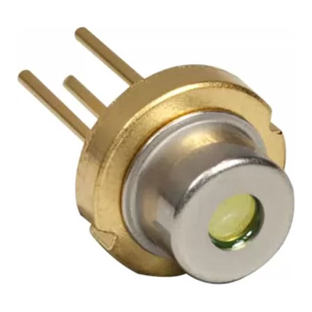 TO56
PLD905-140W-M
905 nm pulsed laser diode, 140 W nominal family, 4-stack emitter and TO56 package variants.
Related reading
905 nm vs 1535 nm vs 1550 nm: choosing a wavelength for ranging and LiDAR
The wavelength decision sets your detector, your eye-safety class, your maximum usable energy and your weather performance. Here is how the three bands actually compare for ranging work.
DetectorsChoosing the receive side: avalanche photodiodes vs PIN photodiodes
Most of a ranging link's margin is recovered at the receiver, not the transmitter. Here is when an APD earns its 10x price, how gain and noise trade off, and what the specification numbers actually mean.
Selection guideHow to choose a 905 nm pulsed laser diode: from range target to part number
A repeatable procedure for turning a range requirement into pulse energy, pulse energy into peak power and pulse width, and peak power into the smallest package that survives your duty cycle.