












Selection guide
How to calculate peak power of a pulsed laser diode
Start with optical pulse energy, then verify waveform, electrical input and thermal limits. Average power divided by duty cycle is only the first step.
Updated 2026-10-29 · 6 min read
1. First define which peak power you need
A laser datasheet may quote optical peak power, peak forward current, or electrical pulse power. These numbers are not interchangeable. For an optical link budget or range calculation, use the optical peak power after the package window, lens, FAC and any fiber coupling.
The distinction becomes important when a driver can deliver 10 A but the laser and optical train convert only part of that electrical pulse into useful light. Always state whether a calculation starts from measured optical average power, pulse energy, current, or a datasheet peak-power entry.
2. Use the three core equations
For regularly repeated pulses, duty cycle is pulse width multiplied by repetition rate. For a rectangular pulse with an FWHM equal to its full width, the following relations apply:
Keep the units consistent. A pulse width is usually nanoseconds, so convert it to seconds before dividing. For example, 100 ns is 100 × 10-9 s.
3. Work through a real example
Take a 180 W optical pulse, 100 ns wide, repeating at 3 kHz:
The inverse check is equally useful. If a photodiode measurement gives 10 mW average at 10 kHz, the pulse energy is 1 µJ. At 100 ns FWHM, a rectangular pulse would have 10 W peak optical power.
4. Correct for a non-rectangular pulse
Real laser pulses have rise and fall times. Define a shape factor k from the pulse energy and the peak amplitude:
For an ideal rectangle, k = 1. A Gaussian pulse has k ≈ 1.0645, so its crest is slightly lower than the rectangle result for the same energy and FWHM. A triangular pulse has k = 0.5; it therefore needs twice the peak amplitude to carry the same energy.
| Idealized pulse | Shape factor k | Peak from energy |
|---|---|---|
| Rectangle | 1.000 | E / t |
| Gaussian | 1.0645 | E / (1.0645 t) |
| Triangle | 0.500 | 2E / t |
If rise and fall are slow or the waveform is asymmetric, measure the pulse with a calibrated detector and integrate the area directly: E = ∫ P(t) dt. The measured energy, not the oscilloscope’s highest sample, sets the useful peak estimate.
5. Keep optical and electrical peak power separate
Electrical pulse power is approximately voltage times current during the flat part of the pulse. Optical peak power is lower by the conversion efficiency: Popt = η × Vf × Ipulse. A 5 V, 10 A pulse is 50 W electrically; at 35 % wall-plug efficiency, it produces about 17.5 W optically.
This rough conversion is useful for sizing a driver, but it is not a substitute for an optical measurement. Forward voltage changes with current and junction temperature, and efficiency falls at high current or high temperature. In short-pulse operation, driver rise time and loop inductance also change the delivered energy.
6. Verify the result against ratings and heat
A mathematically correct peak value can still be unsafe. Check the datasheet’s maximum peak current, pulse width, duty cycle, case temperature and allowed current derating together. Peak power, pulse width and repetition rate form a set; none is an independent operating point.
Estimate average heat rather than average optical power: Pheat,avg ≈ D × (VfIpulse − Popt), plus any leakage and driver losses. A TO56 emitter that looks comfortable at one pulse width may overheat when repetition rate doubles, even if the requested optical peak stays unchanged.
7. Use a five-step calculation workflow
- Record the measured average optical power, or the required pulse energy for the link budget.
- Record pulse width, repetition rate and duty cycle from the actual driver waveform.
- Convert all time values to seconds and calculate pulse energy.
- Divide by the effective pulse width, or apply the waveform shape factor.
- Check peak current, average heat, duty-cycle derating, temperature and laser-safety limits.
Use the peak-power calculator for the arithmetic, then compare the result with the device’s absolute maximum ratings. The companion article on peak power, pulse width and duty cycle explains how the result changes system range and resolution.
Calculators
Calculate with this datasheet
Each calculator below opens with this part's datasheet numbers already filled in, in the units the fields ask for.
Transmitter Pulse Parameters
Pulse energy, average power and duty cycle from datasheet peak power, pulse width and repetition rate, for 905 nm PLD and 1535 nm erbium-glass transmitter selection.
Pulse energy 18 µJ · Peak power 180 W · Pulse width 100 ns · Repetition rate 3 kHz · Duty cycle 0.03 % Laser FundamentalsPulse Peak Power
Instantaneous peak power from pulse energy and pulse width.
Peak power 180 W · Pulse energy 0.018 mJ · Pulse width 100 ns Pulses & EnergyDuty Cycle
Ratio of laser on-time to the full period.
Duty cycle 0.03 % · Pulse width 100 ns · Repetition rate 3 kHz · Repetition rate (Hz) 3000 HzProducts
Related products
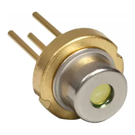 TO56 package
PLD905-180W-M
180 W peak, 905 nm, uncollimated
TO56 package
PLD905-100W-M
100 W peak, 905 nm, uncollimated
TO56 package
PLD905-40W-M
40 W peak, 905 nm, uncollimated
Related reading
How to Calculate Peak Power of a Pulsed Laser Diode
A practical route from average optical power and pulse timing to real peak power, including Gaussian and triangular pulse corrections, electrical efficiency and safe operating limits.
Selection guide905 nm vs 1535 nm vs 1550 nm: choosing a wavelength for ranging and LiDAR
The wavelength decision sets your detector, your eye-safety class, your maximum usable energy and your weather performance. Here is how the three bands actually compare for ranging work.
DetectorsChoosing the receive side: avalanche photodiodes vs PIN photodiodes
Most of a ranging link's margin is recovered at the receiver, not the transmitter. Here is when an APD earns its 10x price, how gain and noise trade off, and what the specification numbers actually mean.
Selection guideHow to choose a 905 nm pulsed laser diode: from range target to part number
A repeatable procedure for turning a range requirement into pulse energy, pulse energy into peak power and pulse width, and peak power into the smallest package that survives your duty cycle.