Stage lighting teardown
Anatomy of an RGB stage laser
A stage laser is a colour engine. Three diode banks are collimated, combined on dichroics, steered by a scanner and projected as a graphic; every loss between the diode and the output window is paid for in white-point budget. Pick a subsystem from the reference bill of materials and drop it on the cutaway to see the parameters and the catalogue parts behind it.
- 1Wählen Sie ein Teil aus der Stückliste.
- 2Ziehen Sie es auf das Modul oder klicken Sie einfach die Karte an.
- 3Lesen Sie seine Aufgabe, seine Parameter und die Bestellnummern dahinter.
Stückliste
Jedes Teil, ein optisches Budget. Ziehen Sie eine Karte auf das Foto oder klicken Sie sie an - das Feld daneben füllt sich mit den Parametern dieses Teils.
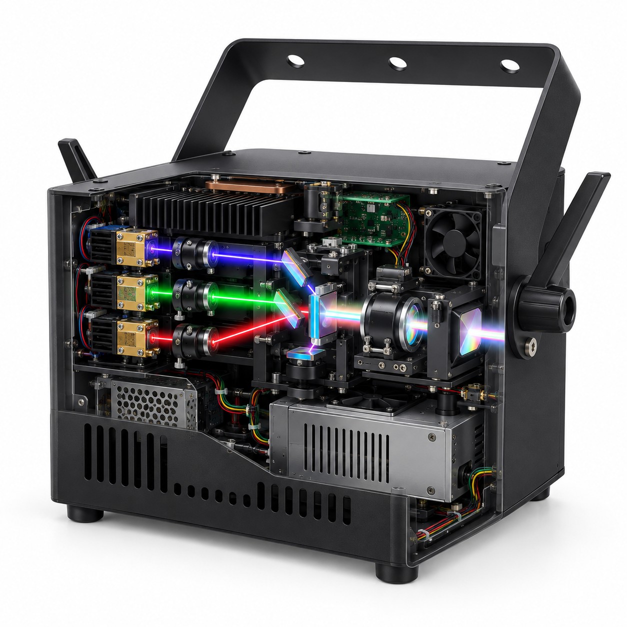
Teil hierher ziehen oder eine Karte in der Stückliste anklicken
A teaching cutaway, not an assembly drawing. The laser banks are on the left, the combining dichroics at the centre, the scanner and projection optics on the right, and the driver and PSU below.
Die Positionen der Komponenten sind ein Lehrschema, keine Montagezeichnung: Anordnung und Explosionsdarstellung sind Richtwerte. Parameterwerte sind die der verlinkten Spezifikation.
Jedes Teil, Parameter für Parameter
Dieselben Zahlen wie in der interaktiven Ansicht, in Tabellen, die Sie lesen, durchsuchen und zitieren können.
450 nm blue laser Colour source
Sets the blue end of the colour gamut and the alignment reference for the first dichroic. In a white-light mix the blue channel usually carries the least visually efficient light, so its beam quality and stability matter more than its headline wattage.
| Wavelength range | 430 - 463 nm |
|---|---|
| Rated output | CW 5 - 5.5 W per emitter |
| Power offered on this line | 5 - 5.5 W collimated | 3 W fibre | 30 mW reference |
| Package | TO9 / LD bank (8 x LD + collimation) |
| Fibre delivery | 400 um multimode, SMA (3 W version) |
| Alignment source | 30 mW single-mode, FC/PC |
| Stage-fixture power class | Collimated emitter | fibre module |
520 nm green laser bank Colour source
Carries most of the perceived brightness, so a small loss here is a visible loss in the projected image. The combining dichroic passes or reflects the whole 510 - 532 nm band, and the emitter spread inside that band is what the white-point trim has to absorb.
| Wavelength range | 510 - 532 nm |
|---|---|
| Rated output | CW 1 - 1.5 W per emitter / 13.5 W bank |
| Operating mode | CW |
| Package | TO9 / TO90 / LD bank |
| Beam | Collimated; square or line spot after shaping |
| Operating case temperature | 0 to +60 |
| Qualified sources | 3 - Sharp, HiLaser, Nichia |
| Spread across sources | Peak wavelength 510 - 532 nm across sources; threshold 0.10 - 0.32 A; operating current 1.4 - 2.0 A at the rated output. |
638 nm red laser bank Colour source
Supplies the red primary and, in a white mix, the colour that is easiest to clip without the eye noticing. That makes it tempting to under-power; the better trade is usually a larger red emitter and a colder heatsink, because the combining edge and the scanner aperture are fixed by the other two lines anyway.
| Wavelength range | 632 - 644 nm |
|---|---|
| Rated output | CW 500 mW - 1 W |
| Operating mode | CW |
| Package | TO56 |
| Beam | Collimated; square or line spot after shaping |
| Operating case temperature | -10 to +40 |
| Qualified sources | 3 - Sharp, Mitsubishi Electric, HiLaser |
| Spread across sources | Peak wavelength 632 - 644 nm across sources; threshold 90 - 180 mA; operating current 660 - 1200 mA at the rated output. |
Fast-axis compression and collimation Beam shaping
Sets the beam height and divergence that every downstream optic sees. If the three channels leave this stage with different heights, the combiner can be aligned for one colour only; if their divergences differ, the spot grows at different rates across the scan field and the white point shifts with angle.
| Channels shaped here | 450 nm | 520 nm | 638 nm |
|---|---|
| Function | Fast-axis compression, collimation and pointing |
| Lens configuration | FAC + collimator, one set per colour Von Ihrem Entwurf festgelegt |
| Coating band | Visible broadband: to be specified Von Ihrem Entwurf festgelegt |
| Output divergence | To be measured after assembly Von Ihrem Entwurf festgelegt |
| Output beam size | To be measured after assembly Von Ihrem Entwurf festgelegt |
| Mounting | Adjustable kinematic mounts Von Ihrem Entwurf festgelegt |
RGB dichroic combiner Colour combining
Turns three separate colour budgets into one white-point budget. Every reflection and transmission loss here is wavelength-dependent, so a coating that is 2 % low at 638 nm changes the colour balance even when the red laser is still at full power.
| Combiner type | Dichroic mirror set on a common axis Von Ihrem Entwurf festgelegt |
|---|---|
| Channels combined | 450 nm | 520 nm | 638 nm |
| Coating edges | To be specified from measured source bands Von Ihrem Entwurf festgelegt |
| Transmission / reflection loss | To be measured per channel Von Ihrem Entwurf festgelegt |
| Clear aperture | To be specified with the beam size Von Ihrem Entwurf festgelegt |
| Alignment tolerance | To be specified with the scanner aperture Von Ihrem Entwurf festgelegt |
| Function | Combine three colours onto one axis |
Scanning galvo and output optics Beam steering
Defines the scan field, the spot size across that field and the maximum angular speed. A beam that fits the combiner but overfills the galvo mirror loses power at the edges of the scan and clips the graphic; a beam that is too small makes the spot diverge faster than the projection lens can correct.
| Scanner type | Two-axis galvanometer Von Ihrem Entwurf festgelegt |
|---|---|
| Scan angle | To be specified with the projection lens Von Ihrem Entwurf festgelegt |
| Scan speed | To be specified with the graphic and ILDA signal Von Ihrem Entwurf festgelegt |
| Input aperture | To be specified from the combined beam Von Ihrem Entwurf festgelegt |
| Mirror coating | Visible broadband: to be specified Von Ihrem Entwurf festgelegt |
| Output optics | Relay / expander and output window Von Ihrem Entwurf festgelegt |
| Safety shutter | Required by the final laser class Von Ihrem Entwurf festgelegt |
Laser driver and modulation board Drive electronics
Sets the operating point of every emitter. A driver that is stable at full power but noisy at 5 % will make the low end of the dimming curve look dirty; one without a hard current limit can destroy a laser during a scan fault. Protection is part of the colour performance, not a separate safety feature.
| Colour channels | 3: 450 nm | 520 nm | 638 nm |
|---|---|
| Modulation | Analog or PWM: to be specified Von Ihrem Entwurf festgelegt |
| Control interface | DMX / ILDA / custom: to be specified Von Ihrem Entwurf festgelegt |
| Current stability | To be measured over case temperature Von Ihrem Entwurf festgelegt |
| Protection | Over-current, over-temperature, interlock Von Ihrem Entwurf festgelegt |
| Blanking | To be specified with the scan speed Von Ihrem Entwurf festgelegt |
| Function | Drive, modulate and protect the three colour channels |
Power supply and thermal system Power and thermal
Holds the emitters at a stable case temperature. Wavelength drift and output power both move with temperature, and the three colours do not move equally; a thermal design that lets the red bank run hotter than the green will change the white point over a show even if every driver current is constant.
| Input power | To be specified from the fixture rating Von Ihrem Entwurf festgelegt |
|---|---|
| DC rails | Driver and scanner rails: to be specified Von Ihrem Entwurf festgelegt |
| Cooling | Heatsink with fan or ducted air Von Ihrem Entwurf festgelegt |
| Thermal control | TEC optional; case sensors required Von Ihrem Entwurf festgelegt |
| Operating temperature | To be specified for the complete fixture Von Ihrem Entwurf festgelegt |
| Acoustic noise | To be measured at the audience position Von Ihrem Entwurf festgelegt |
| Function | Supply, cool and hold the colour channels at their operating point |
Housing, vents and mounting yoke Mechanical
Turns the optical bench into a product. Vibration from the fan, flex in the yoke and thermal expansion of the case all reach the alignment; a housing that is stiff enough for shipping but transmits fan vibration to the galvo will show up as jitter in the projected graphic.
| Material and finish | Sheet metal: to be specified Von Ihrem Entwurf festgelegt |
|---|---|
| Output window | 450 - 660 nm AR coated: to be specified Von Ihrem Entwurf festgelegt |
| Aperture | To be specified from the maximum scan angle Von Ihrem Entwurf festgelegt |
| Mounting | U-shaped yoke with locking tilt Von Ihrem Entwurf festgelegt |
| Cooling path | Intake and exhaust separated from the beam Von Ihrem Entwurf festgelegt |
| Dimensions and weight | To be specified with the optical bench Von Ihrem Entwurf festgelegt |
| Ingress protection | To be specified and tested Von Ihrem Entwurf festgelegt |
Jeder Parameterwert auf dieser Seite stammt aus dem Katalogeintrag, der die verlinkte Produktseite erzeugt, sodass die beiden nicht widersprechen können.
Bauteile hinter diesen Parametern
Jede Zahl unten kommt aus demselben Katalogeintrag, der die Produktseite erzeugt. Hier ist nichts neu abgetippt.
450 nm blue
The 450 nm line covers the blue channel end to end: a collimated 5 - 5.5 W emitter for the main path, a 3 W fibre-coupled module for remote delivery, and a 30 mW single-mode reference for alignment. This is the same blue used by RGB stage engines, not a blue-violet pointer wavelength.
520 nm green
Green is where the catalogue has a genuine stage-class part: the collimated 520 nm emitter at 1 - 1.5 W per emitter, or 13.5 W in a bank. The 50 mW single-mode module below it is the alignment source, not a substitute for the bank.
638 nm red
Red has the widest choice: a 0.5 - 1 W collimated TO56 for the stage output, and 70 or 100 mW single-mode modules for alignment. The collimated part is the one that belongs in a full-colour head; the fibre modules are references.
From three diodes to one white beam
The blue line is the 450 nm used by RGB stage engines: a collimated 5 - 5.5 W emitter for the main channel, a 3 W module with 400 um fibre for fibre delivery, and a 30 mW single-mode reference for alignment. The 520 nm group adds a collimated 1 - 1.5 W emitter (13.5 W in a bank) and a 50 mW fibre module; 638 nm covers 0.5 - 1 W collimated and 70 / 100 mW fibre-coupled parts. This is a colour engine, so the three channels are budgeted together rather than treated as interchangeable power classes.
Send the colour budget, not just a wavelength
Tell us the output power per colour, the white point, the scan angle and the aperture, and we will work back to the emitters, the combining edges and the thermal design the fixture needs.